Design for molding is a niche discipline that challenges even the best engineers. There are many considerations that affect the final composition of your part. These design decisions can lead to manufacturing inefficiencies, costly defects, and delays. But, when a designer takes the time to evaluate their design and mitigate risks, there is opportunity for success.
If you want to design production ready parts – this is the guide to get you there.
Plastic Part Design Process:
Step 1: Define End-Use Requirements
The first step in the product development phase is completing a thorough assessment of the product specifications and end-use requirements. A complete product design specification helps other engineers down the value stream understand the required critical design features. This information should also be quantitative rather than qualitative when possible because this data allows for more informed decisions in the design process. Furthermore, quantitative information, rather than qualitative, allows for better informed design decisions.
However, this can be tricky for prototypes due to the lack of part history. If there is no previous data to inform your design decisions, then a prototype may help inform some of those requirements. As the design matures, use the new data as inputs for the final production part.
Step 2: Create a Preliminary Concept Model
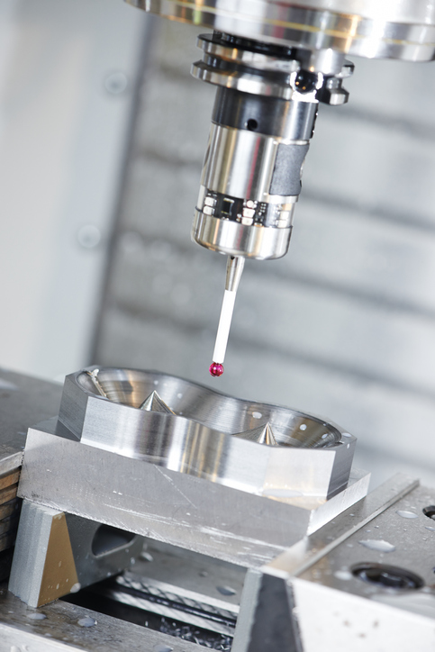
Creating a preliminary model will help your engineering team identify the critical tolerances and design features of the part. This also helps your manufacturing partner understand the features that are critical to quality. If the manufacturer knows what is/ is not critical to quality, they will produce better parts with competitive prices. Your manufacturing partner can also help you optimize part features to simplify tooling.
Step 3: Material Screening
There is an overwhelming array of thermoplastic resin compounds available to you. How do you decide which material best suits your needs? First you want to scout materials with properties that match your end-use requirements. One way to research material properties is to use a resin database like UL Prospector or MatLabs. Start by eliminating the resin families that do not have the material properties you’re looking for such as chemical resistance, thermal properties, or appearance qualities. Once you’ve made your shortlist, compare these material properties side by side. Give yourself enough options so you have flexibility later on.
Step 4: Design Part Around Materials
Now that you have a few materials selected it is time to design your part. But remember, each material has different properties that can affect the geometry of the part. For example, designing with nylon versus a polypropylene would result in thinner wall sections with nylon due to its flow and rigidity properties. Similarly, an HDPE resin would require you to design the part with thicker wall sections which may cause some issues in an assembly where the fit is critical. These are all important factors that make the design process more challenging and cumbersome.
Step 5: Final Material Selection
Once you have compared the design characteristics for each of the selected materials, it’s time to select the one that best matches your needs. Think about this from a few different perspectives: cost, performance, processability, and availability. You want to choose the one that fits the end-use performance criteria. But you also may want to consider how easily that material processes because that can have an effect on the overall manufacturing costs of the product. Hard to process material also results in higher defect rates which triggers higher inspection levels and potentially more scrap. Ultimately, choosing the best material that fits your needs, budgetary and overall performance in both processing and end-use is a key component in successful design projects.
Injection Molding Design Rules
Wall Thickness
Wall thickness is a critical design function for injection molding. This affects how the mold fills as well as the appearance and strength of the molded part. There are three key points to consider:
- Uniform wall thickness
- Nominal wall thickness
- Recommended wall thickness
Uniform Wall Thickness
Uniform wall thickness allows the part to cool evenly and avoid costly defects. When a part consists of varying wall thicknesses it cools and shrinks at different rates. This causes defects such as shrink, warp, and others that affect the strength and appearance of the part. While some designers are okay with these defects in non cosmetic areas, they can cause headaches during inspection if the criteria are not clearly defined. Overall it is best practice to keep a consistent and uniform wall thickness whenever possible.
Nominal Wall Thickness
When a completely uniform wall thickness cannot be achieved, a nominal wall thickness is acceptable. Nominal wall thickness describes the thickness throughout the entire part. This means there are features that are thicker or thinner than the average wall thickness of the part. Be careful, thick and thin walls can affect the molding process negatively and cause quality problems. Let’s define what thick and thin walls are.
Thin Walls: Parts with less than 0.08” of wall thickness are considered thin walls. There are specialized molding techniques that allow you to mold these parts. However, these parts are typically uniformly thin. In non uniform design, thin walls tend to trap air and gas which prevents the plastic from filling the mold cavity completely. This results in short shots – where the molded part is not fully formed. These are typically rejected parts and are thrown away.
Thick Walls: Walls thicker than 0.16” (or thicker than the material recommends) can cause problems too. First, thick walls increase the overall cycle time for each shot. This can impact the cost of each part even if the cycle is just a few seconds longer. Furthermore, thick walls will cool slower than thin walls which causes warp, sink, and voids.
Recommended Wall Thickness
Each resin has a recommended wall thickness specified in its material profile. Whenever you are designing a new part you should refer to these values and adjust your part’s wall thickness appropriately. Below is a quick reference table:
Recommended Wall Thickness by Resin
| Resin | in |
| Acetal | 0.030 – 0.120 |
| Acrylic | 0.025 – 0.15 |
| ABS | 0.045 – 0.14 |
| Nylon | 0.030 – 0.115 |
| PBT | 0.080 – 0.250 |
| PC | 0.040 – 0.150 |
| PEEK | 0.020 – 0.200 |
| PEI | 0.080 – 0.120 |
| PE | 0.030 – 0.200 |
| PPSU | 0.030 – 0.250 |
| PP | 0.040 – 0.15 |
| PS | 0.025 – 0.125 |
| TPE | 0.025 – 0.125 |
| TPU | 0.025-0.125 |
These values are derived from publicly available information. Optimal wall thicknesses can vary depending on the geometry of the part. We recommend reviewing your design with a plastics engineer to optimize the wall thickness throughout the part.
Transitions
If your part requires different wall thicknesses, then the transition from thick to thin needs to be blended smoothly. Sharp steps and corners between different wall thicknesses will hinder the flow of material and compromise the part’s integrity. The best way to avoid this is by using fillets and chamfers to round out the transitions.
- Fillets – rounded corners or edges
- Chamfers – 45deg angled edges connecting two surfaces.
Corners
Where possible, corners should be rounded with proper radii. Rounded corners reduce stress concentrations in the part, which can cause defects that create aesthetic or functional problems. They also minimize plastic shrinkage so that corners are even. Calculating the radius on a rounded corner is simple:
- Internal radius 50% of wall thickness (assuming nominal thickness)
- For the external radius, use your wall thickness measurement and add the internal radius value (R2=R1 +Wt)
- Both internal and external radii need to originate from the same point.
- Parts with equal internal and external radii will end up with a corner that is either too thick or too thin.
- Sharp corners often require EDM machining, a process that is precise but costly.
Ultimately, using rounded corners not only promotes better moldability, they also simplify the moldmaking process making your part easier to manufacture and buy at a reasonable cost.
Draft
Applying the right amount of draft is a crucial part of the design process for injection molding. Draft is an angle applied to vertical walls that allow the part to eject from the mold. Essentially, the draft allows for the steel to clear away from the molded part without damaging it. A good rule of thumb is to use 1 degree of draft per side for every 4 inches of length. Be sure to consider the pull direction, how the mold separates, to determine the draft direction.
A quick note: draft angle specifications vary from material to material and can be influenced by the texture of the mold. To find out how much draft you need to apply, we suggest using the Society of Plastics Industry (PLASTICS) standards and Mold-Tech for guidance.
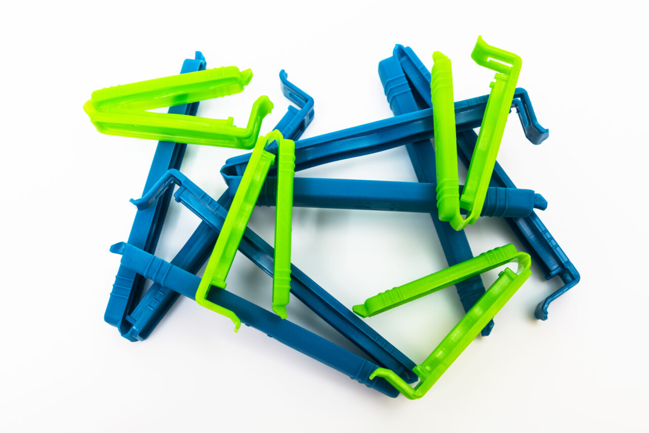
Ribs:
Sometimes, an engineer will design a part with thin walls; reducing material usage, speeding up production, and promoting longer tool life. However, these thin walls lack the load-bearing capacity and do not have the structural strength required for the application on their own. Ribs are a design feature that add strength and support to thin walled parts. Using a vertical rib gives these walls additional strength and can even reduce warp with certain geometries.
Like many injection molding design features, ribs require a bit of homework to design properly. Thick ribs have a tendency to produce sink marks, and thin ribs do not provide enough strength and may potentially end up not fully filled.
Here are some more design rules for ribs:
- Wall thickness: should be 50-60% of nominal wall thickness
- Fillets: should be used at the base of ribs to avoid sharp transitions. An appropriate radius is 25-50% of the nominal wall thickness, but should be no greater than 0.01”
- Height: Keep rib heights to a minimum, no more than 2.5X the wall thickness. If you need more support for taller walls then add ribs no less than 2X the wall thickness from each other.
- Draft: Apply at least 0.5 degrees per side.
Bosses:
Bosses are another popular design feature used in injection molding. These vertical features are used in assembly applications to receive fasteners such as screws, pins, or even smaller bosses. Like ribs, bosses also increase the structural strength of a part when designed appropriately.
Here are a few golden rules to follow when designing bosses:
- Size: the inner diameter of a boss is likely to shrink as the part cools. It is essential that you reference the material’s shrink properties when adding a boss and design the feature accordingly. The overall size of the boss should be between 2-2.5X the size of the inner diameter of the part.
- Thickness: Like many other plastic features, thickness matters. Bosses that are too thick are prone to sink, which can be an eyesore. We recommend that bosses are no more than 60% of the overall wall thickness.
- Location: Place boxes where structural integrity is needed such as screw holes.
- Walls: Alignment when attaching bosses is key. These bosses need to align with other features of the part or mating part to prevent assembly mismatch. Also, avoid thick wall sections when attaching a boss to a wall. One option is to core out sections of the thick area to make a uniform wall section.
Parting Lines:
A parting line refers to the line created at the point where the two halves of the mold meet when closed. Depending on the aesthetic requirements and geometry of the part, the parting line can be moved around to fit your needs. There are a few places where parting lines can be placed to help simplify the mold construction, such as sharp corners. And there are some places where parting lines should not be placed such as on filleted surfaces. Finally, it is important to note some of the common defects that happen at the parting line which is an indication of the overall health of the mold. Defects such as parting line flash, mismatch, and stress marks are indications that either some tool work needs to be done or that the mold was not installed properly.
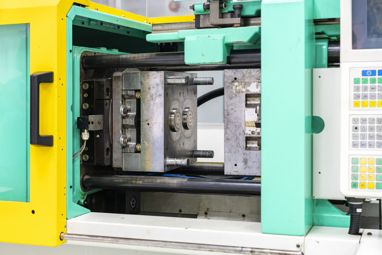
Gates:
A gate refers to an opening in the injection mold where molten plastic enters and fills the cavity. There are many types of gates in injection molding. Some gates enable better material flow through the cavity which allows the mold to fill fast and complete. While others offer better appearance results or eliminate extra manufacturing steps. This all depends on the part geometry and features.
Before we dive into the different types of gates we need to discuss two critical decisions: location and size.
Gate Size: The size of the gate is important because it controls the flow volume of the material into the mold. Larger parts, and materials with a low melt flow rate (MVR), need larger gates. If the gate is undersized, the part is at risk of not fully forming. However, oversized gates are harder to trim and waste material. Thankfully, thermoplastic materials come with a gate sizing specification which can be used to calculate the proper size for the gate.
Gate location: The gate location has a huge impact on the final part quality. For instance, the location determines the direction of material flows, where weld lines appear, and what features are the last to fill. This can result in defects such as short shots, voids, warping and others that can occur. To avoid potential defects, we offer mold flow analysis and a comprehensive mold design review.
Here are the different types available:
- Edge
- Fan
- Tab
- Sprue
- Diaphragm
- Ring
- Spoke
- Hot tips
- Sub
- Pin
Ejection
Ejection in injection molding is the process of removing the molded part from the mold cavity. This is one of the critical phases in the injection molding cycle, so ensuring your part can eject from the mold without any issues is crucial. In order to do this, we need to consider ejection throughout the design process. There are several key factors that affect the parts ability to eject, and of course, some golden rules too.
Let’s look at a few of these factors:
- Draft Angles: Draft angles reduce friction during ejection, making it easier for the part to release smoothly from the mold. Deep parts require steeper drafts
- Ejector Pins and Contact Points: Place ejector pins on flat, sturdy areas of the part to avoid visible marks and damage. Avoid positioning pins near delicate features, thin walls, or unsupported edges, as these can break or deform during ejection.
- Wall Thickness and Reinforcement: Thin or sharp-edged features are prone to breakage. To improve ejection, maintain consistent wall thickness and add ribs or fillets to reinforce critical areas. Avoid thin walls near ejector pins, as they may deform or tear.
- Textured Surfaces: For textured or rough surfaces, increase draft angles to prevent sticking and ensure a clean release.
- Undercuts and Core Pulls: Avoid undercuts where possible, as they complicate ejection and may require additional mechanisms like core pulls. Designs with minimal undercuts allow for simpler, more reliable ejection.
The information provided in this guide is public information and should be used as a suggestion for part design. Specifications with more stringent requirements may require further investigation. Contact us for help and we can do a comprehensive DFM review with you and your team.