
How to Cut Your Assembly Time by 48% with One-Piece Flow

What is the question burning in the back of the mind of manufacturers today? The same as it’s been for decades – how do I reduce my costs and increase productivity? With the mix of labor force struggles, high demand for products, and strained supply chains, maximizing efficiency is more important than ever. That is because time is a limited resource and already spread thin in most factories. So, how can we maximize our use of time to bring costs down and produce more? One way is to design an efficient assembly process with a one-piece flow.
In this post, we will introduce the concept of one-piece flow assembly lines. We will discuss why this process is more efficient compared to other assembly processes. For example, we will focus on the difference between batching and one-piece flow. Additionally, we will link to a video that illustrates how much time you can save with this process.
Ready. Set. Assemble!
What is One-Piece Flow?
Flow is the movement of a product from one operation to the next in a value stream. With a one-piece flow, the goal is to plan the workflow based on the products’ needs while eliminating wasted movements. In other words, with the one-piece flow, you want to cut touches that interrupt workflow and that aren’t value-added. Ultimately, this allows you to move between operations without work-in-process (WIP) between them.
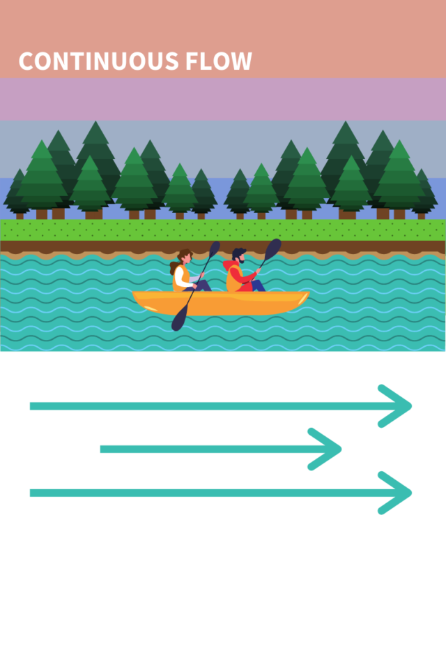
To demonstrate, some real-world examples of continuous flow are flowing water and wind. These two elements flow continuously until they are restricted by obstacles (rocks, trees, structures), constricting their flow. Below is an illustration of this happening in nature.
As you can see from the illustration, the canoes can travel down the river with ease when there aren’t any obstacles. When we introduce objects that interrupt that flow our adventurers have a much harder time traveling downstream.
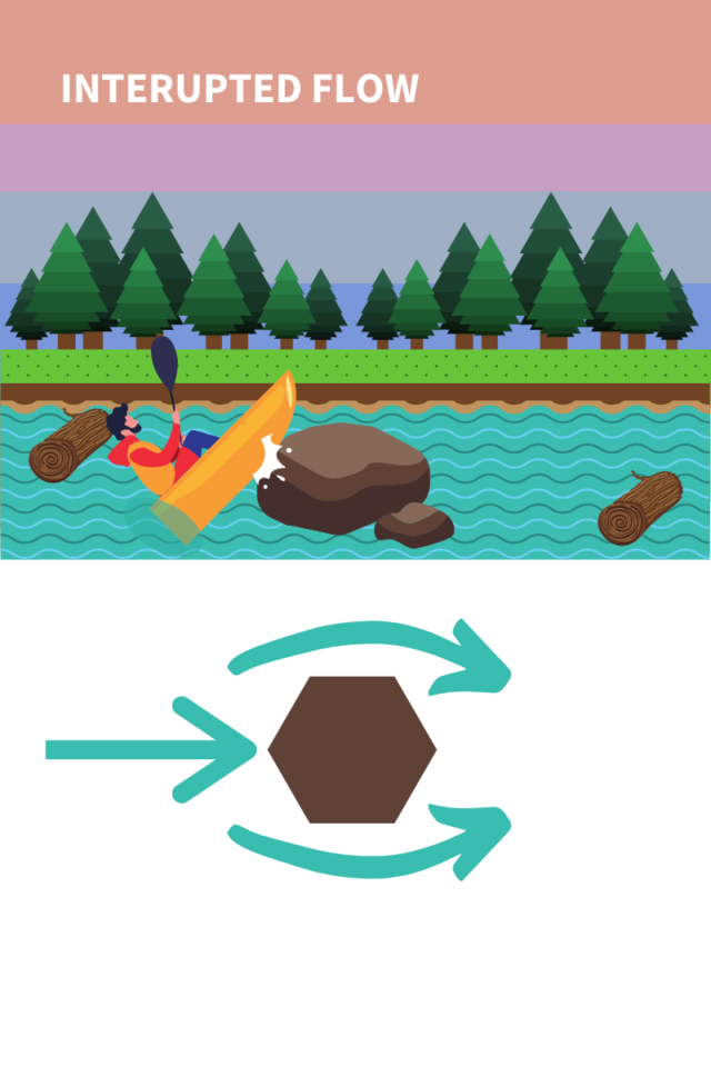
Bottlenecks:
On the production line, this creates what we know as a bottleneck. A bottleneck is a process in an assembly line with limited capacity that affects the capacity of the entire line. In other words, a bottleneck constraint occurs when there is too much work/ supply at a specific point in a process. Ultimately, a bottleneck holds up the rest of the operation up and down the value stream. This results in longer delays and higher production costs.
Where Did One-Piece Flow Originate?
Single-piece flow comes from the lean manufacturing practice of just-in-time (JIT). The well-known car manufacturer- Toyota -pioneered this idea in the mid 20th century. With just-in-time, manufacturers produced components only as needed and nothing more. In other words, with a one-piece flow, the manufacturer delivered a product only when the customer demanded one.
This lean system resulted in many manufacturing revelations. For one, it helped standardize many processes and workflows. But more importantly, one-piece flow helped cut inventory build-up and cost. Because of this, manufacturers were able to fill orders at the rate of customer demand without having to back stock pallets of products. All in all, by optimizing their workflow manufactures reduced their inventory cost, used time and resources more efficiently, and increased their output.
Why is One-Piece Flow Better Than Batching?
Batching is the process of finishing one operation for a whole batch of pieces before moving on to the next step. For example, for a batch of 10 parts, an operator would complete step 1 for all 10 parts before moving onto the next step. Most of those unfamiliar with lean manufacturing would accept this as common sense and run with it. Some would even argue that it is an efficient method.
Not so fast!
What happens with batch processing is this massive pile-up of inventory between each station. We know this as work-in-process (WIP). And when there is WIP someone is waiting for that process to finish. That someone could be the next person on the line, or a customer waiting for their product.
Waiting time = wasted time.
Check out this illustration showing the time-saving between one-piece vs batch processing:
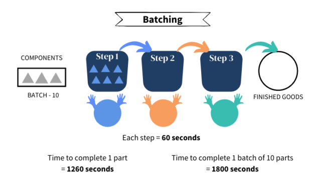
In this example, when we use single piece flow we reduce the assembly time by 40%!
Let’s break down what we are seeing above in batch processing:
Operator 1 (Blue) has to complete Step 1 for all 10 parts in the batch. She then passes all 10 pieces to the next operator.
Operator 2 (Orange) gets her hands on the batch after patiently waiting. Now, she must complete Step 2 for all 10 pieces. There are now 10 parts that are WIP. * Side note- If this operation were to continue past these 10 parts there would actually be 20 parts in WIP and 30 in the next step.
Finally, Operator 3 (Green) initiates Step 3. After the first 60 second cycle, we finally have 1 finished good. But, it has taken us 21 minutes to complete just 1 part! At the end of this operation, they will have spent 30 minutes on these 10 parts.
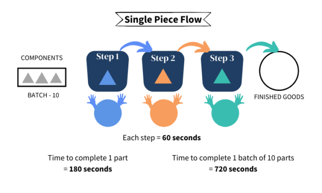
Now, let’s move over to the single-piece processing graphic:
Operator 1 (Blue) takes one piece and completes step 1 in 60 seconds. She moves the finished part to the next operator and grabs a new part. She’s moving fast!
Operator 2 (Orange) ‘pulls’ the first part to her station and finishes her step in 60 seconds. Again, she moves the part onto the next station and pulls a new piece. We’re on a roll now!
Operator 3 (Green) now has the first piece. There are a total of 3 pieces that are WIP and 7 that have yet to be touched. But, once this step is completed they will have completed their first finished good in 3 minutes! Also, they will now churn out a finished good every 60 seconds because there is a continuous flow. After just 12 minutes, the second line has finished their batch of 10 parts.
See the difference? If this wasn’t clear enough, check out this animation.
Now that you know what you (might) be missing out on, we’ll show you how to set up your workstations for one-piece flow.
How To Achieve Continuous Flow
Yes, the one-piece flow has many advantages. Yet, to implement this process you need to meet certain requirements. Without these requirements, the one-piece flow will be near impossible to achieve.
Here are those requirements:
- Maintain 100% machine uptime (or as close to 100% as possible).
- Work, resources, and time must be divided evenly amongst workstations.
- Work-in-process (WIP) must be limited to one item in any station’s queue.
- Time to complete a task must be measurable and repeatable.
- Time to make one-piece must be scalable to customer demands (takt time).
- The quality of resources must be consistent. Inconsistent quality equals poor defect rate.
- The operation must be able to consistently produce good results.
Variation is the enemy of continuous flow. To achieve an efficient flow, you have to cut variation from the process. If these conditions above aren’t met, then ultimately you will not achieve a one-piece flow down your value stream. After all, it is possible that your product is not suitable for one-piece flow.
But if you do have what it takes to kick the variation bug, then here are the 6-steps to creating your own continuous flow workstations
6 Steps For Creating Continuous Flow Workstations
Step 1: Design a connected flow
A connected flow involves linking each process step within a value stream. In other words, you can establish an underlying relationship between each processing step in a connected flow. Each manufacturing step is either directly related, or related by a pull system like FIFO. Ultimately, the goal of this relationship is to move the product from step to step with little to zero waiting time.
Step 2: Determine whether the workstation is product-focused or mixed
Basically, the difference between product-focused and mixed is the number of products that occupy that workstation. For instance, if the workstation focuses on one product then you can focus on that process. However, the demand for this product must be high enough to maintain a continuous flow.
If there is a mix of products that need assembly at this workstation, then the rules change a bit. For example, if the workstation has to accommodate product A one hour and product B the next, you’ll need to use a mixed station. With a mixed station, the goal is to minimize changeover time. Changeover time is the time between the last good product run and the first good product of the new run. As a general rule, changeover time must be less than one takt time.
Step 3: Calculate Takt Time
Takt time– a measurement of customer demand expressed in units of time. Takt time allows you to keep a pulse on your customers’ demands without under or over-producing products. This is another concept of lean manufacturing and just-in-time where the customer only receives a product when they ask for one. Ultimately, this drives production and inventory costs down.
To calculate takt time use the following formula:
Takt time= Available work-time per shift / Customer demand per shift
Step 4: Determine the processes and time required for making one piece
Step 4 involves conducting an extensive time study on each of the individual processes within the whole operation. First, you need to identify each step in the assembly process from start to finish. Then, you will want to follow a single product through the process from start to finish. Record the time it takes to complete each step as you move through the process. Once you finish, go back through and time each step repeatedly. From this data, take the lowest repeatable timestamp and use it as your baseline going forward.
Can your recorded times match up to meet takt time? If not, you may need to reevaluate your processes and/or equipment.
Linkable content – How to conduct a time-study.
Step 5: Create a lean layout using elements of 5-S
Creating a lean layout is a difficult, but necessary activity. The goal at this stage is to limit wasted movements within the work cell. For example, placing equipment and material at the point of use is a great way to cut wasted movement. On the other hand, if the operator must turn around every 5 seconds to grab a tool then they are wasting movements. In short, wasted movement slows down the line which creates more WIP- a cardinal sin in this discipline.
Another great way to cut waste is through the workstation’s design. The most common design, and perhaps the best, is the U-shaped workstation. This gives an operator full access to resources with limited movements. Yet, there are some instances where a U-shape is not possible due to space constraints. You can experiment with other shapes to find out the best for your situation.
Linkable content: Case Study- Why the popular video game Overcooked is a perfect example of bad cell design.
Linkable content: What is the 5-S methodology
Step 6: Balance the workstation and create standardized work instructions.
The last step is to balance the workstation and deploy a standardized process for splitting up the work time. For example, our earlier segment showed a 3-step setup with each step requiring 60 seconds of work-time. The entire process takes 3 minutes to complete, which can be split up between 3 operators for balance. If we added an operator, then we would split the time amongst the 4 – equalling 45 seconds each. Similarly, we can subtract an operator and split the 3 minutes in half, 90 seconds each.
Again, the way to balance the cells depends on the number of steps and how much time each step needs. There is a formula that tells you how many operators you’ll need to be successful. That formula is shown below:
Number of operators = Total work content/ Takt time
Ex: 720 seconds / (28800 seconds in a shift / 100 parts per shift demanded)= 2.5 operators
Oops! We have half an operator leftover! This is called an inconvenient remainder. With these remaining operators, it is difficult to balance the assembly line. You can reallocate these operators/ activities to resource management to balance the line. Or, you can reevaluate your value stream to make it more efficient. To do this you need to cut steps out of the operation or reduce the time needed to complete the longer steps.
In conclusion, one-piece flow is one of many ways to optimize an operation. Most of the time, continuous flow is achievable with one, if not all value streams. But, that is if you have the right resources. If not, then it is important to continuously improve processes to try and achieve this flow. Ultimately, this is the way manufacturers can increase output, reduce costs, and keep customers stocked. If you don’t have the resources, for whatever reason, then working with a contract manufacturer would be the best course of action.