Surface finish is a critical aspect of many plastic parts, as it can affect the part’s performance and aesthetic appeal. To ensure that the surface finish of a plastic part meets specifications, it is important to use proper measurement techniques that are accurate and repeatable. In this post, we will discuss the use of Geometric Dimensioning and Tolerancing (GD&T) principles and profilometers for measuring surface finish on a plastic part.
What is Surface Finish?
Surface finish refers to the roughness, waviness, and lay of a surface. In other words, it is characterized by the micro-geometry of the surface, including the size, spacing, and distribution of surface features. These features can include surface roughness, such as peaks and valleys, and surface waviness, which refers to the undulations in the surface.
Why is Surface Finish Important?
Surface finish is important for a variety of reasons. For example, it can affect the performance of a part by influencing factors such as friction, wear, and corrosion resistance. Additionally, a smooth surface finish can improve the aesthetic appeal of a part and increase its marketability.
How is Surface Finish Measured?
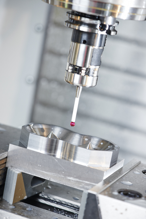
There are several methods for measuring surface finish, including visual inspection, tactile inspection, and instrumentation-based measurements. The most commonly used instrument for measuring surface finish is a profilometer. Profilometers use a stylus to scan the surface of the part and measure the variations in surface height. Then, the data collected by the profilometer is processed to calculate the roughness parameters of the surface, including roughness average (Ra), root mean square roughness (Rq), and more.
Using GD&T Principles for Surface Finish Measurement
In order to ensure that the surface finish of a plastic part meets specifications, it is important to use a consistent and repeatable measurement method. This is where GD&T principles come into play. GD&T is a system of symbols and rules used to define the size, shape, orientation, and location of a part. With GD&T symbols and rules, designers can specify the surface finish requirements of a part, including the maximum and minimum allowable roughness parameters.
For example, the GD&T symbol for surface finish is a wavy line that is placed adjacent to a feature of size. The wavy line represents the surface roughness and the number next to it represents the maximum allowable roughness in microinches (µin). By specifying the surface finish in GD&T, designers can ensure that the part is manufactured to the correct specifications and that the surface finish is accurately measured.
Conclusion
Measuring surface finish on a plastic part is an important step in ensuring that the part meets performance and aesthetic specifications. By using GD&T principles and profilometers, designers can specify the surface finish requirements of a part and ensure that the measurement is accurate and repeatable. By using these techniques, manufacturers can produce high-quality plastic parts that meet the needs of their customers.
For more information on how we can help you achieve a desired surface finish, please reach out to our engineering department at the number on our contact page.
The mold build designed to shorten time-to-market and reduce tooling costs.
Have you ever approached an injection molder looking to source a quote for a project still in the development phase? If so, you might have balked at the initial tooling price. Why on Earth would you invest so much upfront on a project you’re not sure will succeed on the market?
Well, there’s another tooling option that you might not be aware of – MUD units. In a nutshell, a MUD unit is capable of making quality, precision parts without the price tag. This is the perfect tool build to produce a short run for your engineering or market tests.
In this article, we’ll go into more detail about what a MUD unit is and how it works. You’ll also find the benefits of this type of build and its capabilities. Finally, we’ll send you home with some notes to take back to your engineering team. If you have further questions, please reach out!
What is a MUD Mold Base?
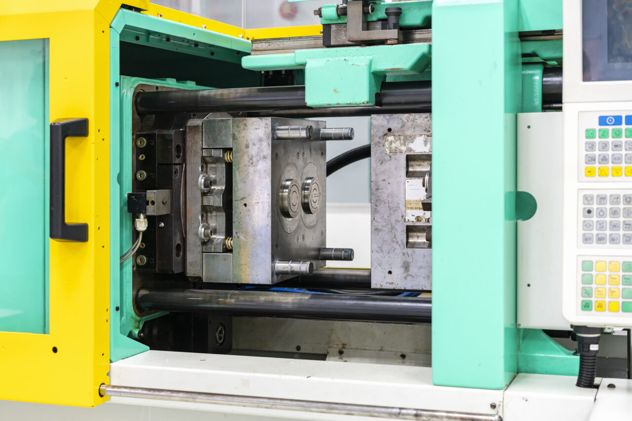
A MUD – or Master Unit Die – is a modular mold base that houses interchangeable cavity and core inserts. These builds use a standard-size mold frame that can be left in an injection molding machine while a mold technician completes a changeover. In other words, the molder can change molds by simply removing the core and cavity inserts and replacing them with another compatible set. This is ideal when you have multiple product configurations or a product still in development.
What Does a MUD Base Do?
MUD bases are a cost-effective, yet productive alternative to full-sized molds (full chase). The modular nature of a MUD unit allows molders to quickly switch mold configurations or even to other products with minimal downtime. Once the mold frame is in place, the molder can quickly change out the core and cavity inserts in favor of a different set. In just a few steps, the manufacturer can go from molding one product to another.
Choosing a mold base will still allow you to build *thousands of parts with quality and precision. In fact, the ability of these tools is on par with small and medium-run injection molding tools. Furthermore, many mold builders can build these while incorporating hot runners and other mold accessories to drive better manufacturing results.
MUD Bases and Project Development
It is true – MUD bases are perfect for projects that are still in development or going through design changes.
Having removable inserts makes troubleshooting and making tooling adjustments much easier. This is mainly due to the technician not having to remove an entire mold base. In addition, the mold builder can work quicker by not having to disassemble multiple mold plates.
These inserts are typically made of P20 or H13 steel. The former is softer and therefore easier to machine. This makes modifying the tool to address a design change much more feasible. However, drastic changes to a design may require building new inserts completely.
Ultimately, this is better than having to build an entirely new mold.
Benefits of MUD Bases
We’ve covered a few of the benefits of MUD bases already. Here is a summary of those benefits:
· Setup time reduced from hours to minutes
· Quick/ easy to modify without removing an entire mold frame
· Minimal production downtime
· Easy to handle, use, install, and maintain
· Lower tooling build cost as you only need to purchase in A& B inserts and not the entire mold base.
· Lower labor costs by reducing the number of techs working on one mold.
· Speed to market is improved by reducing machining time and workload.
· Sustainability – the frame can be reused with other inserts.
· Supply chain flexibility to support just-in-time scheduling
Types of MUD Bases and Frames
As we discussed, the core and cavity inserts have a ton of customization options. Mold frames on the other hand do not.
Mold frames are more standardized in size and build. For the inserts to have a proper fit and truly be modular– you need the proper frame shape. Fortunately, there are a handful of shapes available that allow you to be more flexible with your insert configurations.
Here are a few of the main ones:
U-frame: standard single insert
H-frame: standard double insert
Double H-frame: Standard 4 insert
E-Frame: side by side double insert
What You Do and Don’t Need to Know (Conclusion)
It is unlikely that you will have to decide for yourself which mold frame to go with. Your injection molder will have the insight to use the best frame for your MUD unit.
On the other hand, it is up to you to understand the capabilities and limitations of the MUD unit. While it is possible to have a MUD unit produce hundreds of thousands of parts – that is beyond its life expectancy. Furthermore, you should expect to see wear on the tool where there are moving parts (slides, cores, pins, etc.). This can cause issues with production and impact the final part quality or result in unplanned downtime.
Therefore, you should have a conversation with your molding partner to see if building a high-volume production tool is right for your project. At that point, you can plan an appropriate timeline for ramping up production and minimizing potential downtime.
Launching a new product soon?
If you’re planning to launch a project in the next year and need a MUD unit for market testing – we can get one built for you! Visit our website and fill out an RFQ form to start the process. We look forward to working with you!
Typical Steel Properties For Injection Molding Tools
Properties
Carbon steel
Alloy steel
Stainless steels
Tool steels
Density (kg/m3)
7850
7850
7750 – 8100
7720 – 8000
Elastic Modulus (GPa)
190-210
190 -210
190 – 210
190 – 210
Melting Point (oC)
1425 – 1540
1415 – 1432
1371-1510
1400 -1425
Tensile Strength (MPa)
276 – 1882
756 – 1882
515 – 827
640 – 2000
Hardness (Brinell 3000kg)
86 – 388
149 – 627
137 – 595
210 – 620
Yield Strength (MPa)
186 – 758
366 – 1793
207 – 552
380 – 440
Thermal Expansion (10^-6/ K)
11 – 16.6
9.0 – 15
9.0 20.7
9.4 – 15.1
Thermal Conductivity (W/m.K)
24.3 – 65.2
26 – 48.6
11.2 – 36.7
19.9 – 48.3
This chart for typical steel properties for injection mold tools is to be used for reference only and is public information. Plastics Plus Technology Inc and its partners are not responsible for decisions made based on this information alone.
Process optimization is a great cost-effective way to increase production volume.
Here’s a great example of how we did this for a customer back in 2018 when their orders increased by +200%.
Some context info: The existing process required a secondary machining operation to produce geometries not achievable with an injection mold tool. The injection molding process could easily support the increase in demand, however, the secondary machining operation was slow and could not support the increase in demand without the addition of a second shift operation.
Opening a second shift operation would have required an increase in cost to our customers.
So, we decided to conduct a detailed review of our machining process. First, we conducted a time study to determine if there were any areas of improvement and eliminate wasted time/ movements. In our review, we found there was a “non-value added” time in the process of clamping/ unclamping the part into the fixture. Furthermore, the need for 5 different CNC tooling changes exacerbated this waste.
We identified that by using a toggle clamp we could still hold the part and reduce the clamp/un-clamp time by 31%, a 70.5-second cycle reduction.
Our team then moved on to review the reasons for the need to use 5 different tools. As each tool change took 12 seconds, an additional 60 seconds of “non-value” added time was incurred.
We found that the milling functions were redundant and therefore designed a form tool that could combine operations. These improvements improved the cycle by another 40%. In the end, our process improvement team was able to increase our 8-hour production by 236%. We were also able to reduce our labor cost per part by 62%.
Want similar insights? Subscribe to the Plastics Plus Insider Newsletter and get these and other tips delivered to your inbox monthly.
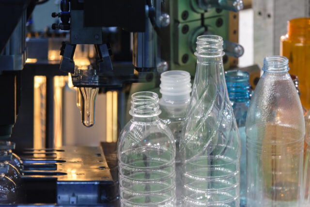
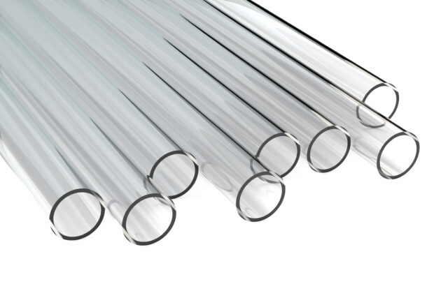
Plastic manufacturing is a popular subject that appears across every industry. From food processing to automotive components, plastic is a staple of the products we use. It’s in our packaging, our transportation, our clothes…it’s everywhere! To meet the high demand for plastic, manufacturers leverage different types of processing capabilities. This includes blow molding, compression, extrusion, rotational, 3D printing, and injection molding. Each one of these methods is capable of producing a specific plastic application. For example, blow molding is best for making plastic bottles, and extrusion is best for tubes. Our service, injection molding, is perfect for mass-producing plastic components.
We’ll discuss these different plastic manufacturing methods in depth throughout this segment. Follow along, or skip to one of the methods of your choice.
What is Injection Molding?
Plastic injection molding is a popular method of making a variety of plastic parts. This process involves melting thermoplastic material through an injection molding machine. First, plastic resin enters the machine via the hopper and enters the barrel. The barrel contains a reciprocating screw, which mixes and melts the plastic. Then, the press injects the molten plastic into a single or multi-cavity mold. The mold clamps shut during injection and open at the end of the cycle. Finally, the cooled part falls from the press and is handled by a machine or an operator.
This is an oversimplified explanation of course, but the capabilities of molding are easy to illustrate. For example, this cycle happens (in most cases) under a minute and sometimes even under 20 seconds. Pair that speed with a multi-cavity mold and you can make thousands of parts a day. Ultimately, this means you can take advantage and scale production quickly.
To wrap up this section (because I could go on) injection molding is fast, scalable, but also repeatable and versatile. The results of injection molding are consistent from run to run, which means you can expect a certain level of quality. And it is versatile because you can make complex 3D shapes. Of course, you have to optimize your design for manufacturability and assembly for it to be moldable. But, if that is taken care of then the possibilities are limitless.
Ultimately, injection molding is best for high-volume production. Whether that application is a medical device, automotive component, or bottle caps; you can produce lightweight, strong plastic parts.
What is Rotational Molding?
Rotomolding is similar in the way that it utilizes a mold to force the plastic to take the desired shape. Except in rotational molding, the polymer is a fine powder that fills the mold. The mold is placed on a rotating arm that operates by moving on a 3-dimensional axis, which helps fill the mold. The mold, while in rotation, enters into an oven that produces heat between 400 and 500 degrees Fahrenheit. The oven encloses the mold for the necessary duration, then moves to a cooling phase. The mold cools under specific conditions dictated by the material and size of the mold.
Rotational molding is a low-pressure manufacturing process. This means that the tooling requirements aren’t as much as other methods, which reduces the cost. For instance, a thin-walled aluminum mold is much less expensive than heat-treated stainless steel used in injection molding. Additionally, there is an opportunity to ‘foam’ rotomolded parts. This means that you can add insulation, floatation, and other capabilities to your product.
Rotational molding is considered a versatile process when it comes to plastic manufacturing. But Rotomolded parts are typically bigger, less precise units that are machined for functionality. So if you want a large plastic unit, like a play structure or a large drum container, rotational molding may be right for you.
What is Blow Molding?
As explained in the introduction, blow molding is great for making plastic bottles. But how does it work? Well, it’s actually like glass blowing but with plastic. You start with a small plastic parison- a rounded mass formed by heating and rolling- and blow gas (air) through it to inflate. Essentially, the small plastic mass inflates according to the shape and size of the mold. Once it cools, the inflated part ejects from the mold.
Blow molding is great for manufacturing one-piece, hollow plastic objects. Like soda bottles! It is also useful for thin-walled applications like plastic storage containers. Like injection molding, blow molding produces high volumes because of its quick cycles. Additionally, there are many thermoplastic materials that are compatible with this process. This creates plenty of opportunities to create specialized products.
What is Compression Molding?
Compression molding is another popular molding method used by automotive part makers. The process is like injection molding, except the mold closes around the plastic during compression. For illustration, the plastic ‘charge is set on the bottom half of the mold. Then, when the press starts the top half smushes the charge into the cavity. The plastic fills the cavity and seeps out into overflow grooves. This is like the runner and gate in injection molding.
Another key difference is that compression molding uses thermoset polymers. This means that after molding, the resulting component must ‘cure’ in a kiln-like oven. Through curing, the component settles into and holds its finished shape.
There are 4 main steps to compression molding:
A two-part metallic tool matching the exact dimensions of the object is produced, installed, and heated to the requirements of the plastic.
The plastic composite is pre-formed to the shape of the tool.
Under pressure, the pre-formed object is inserted in the hot mold and compressed. This pressure ranges anywhere between 800 psi and 2000 psi depending on the thickness of the part.
The part is removed from the tool and any flash on the edge is trimmed off.
The main benefit of compression molding is the ability to use advanced composite materials. These materials include thermosetting resins, glass-reinforced plastics, fiberglass, and other strong materials. With these materials, you can create a wide range of parts for a variety of applications. Also, with compression molding, you can create simple and somewhat complex geometric shapes. To summarize, compression molding is versatile enough for many low and medium-volume production projects.
What is Extrusion Molding?
The initial process of extrusion molding resembles that of injection molding. The extrusion press uses a screw to melt and push plastic resin through the die. A die, unlike a mold, is a hollow form that shapes the plastic as the screw pushes it through. In other words, the die dictates the specific shape and thickness of the manufactured part. The extruded part is then conveyed into a cooling chamber- a water bath or spray booth. At the end of the cycle, a saw or blade cuts the long extruded material in sections of the desired length.
One key feature of extrusion molding is its continuous process. For example, the extrusion press continuously feeds plastic through the die. This creates a long beam or tube of molded plastic that stays intact until it is cut or wound into a spool. If you haven’t picked up on it yet, extrusion molding is great for long, hollow applications. For example, tubes, straws, pipes, and wires are also extruded applications. Also, channel sections are a popular extruded product as well.
What is Additive Manufacturing (3D Printing)
Additive manufacturing is better known as 3D printing. And it is all the rage in the 21st century. 3D printing uses CAD software and 3D object scanners to program hardware (such as a printer) to make an object. In other words, the digital software recreates an object digitally; which tells the hardware how to physically make it in layers. The 3D printer then produces super-fine layers of material in precise geometric patterns. Layer by layer, the printer deposits material until the final product takes form. This can take minutes, hours, or days depending on the object. But, additive manufacturing is still considered an easier way to develop and test prototype products.
While the technology is advancing, additive manufacturing is still behind in volume capabilities. But, as hinted above, you can skip the wait and test prototypes quicker than other molding processes. For example, with injection molding, you would have to spend thousands of dollars to produce a prototype tool. Not only is that expensive, but the lead times on a tool can set your schedule back. Plus, if for any reason the product is redesigned then that is another costly headache. With 3D printing, you can develop and test prototypes in weeks, not months.
Wrap Up
Now you know the basics of plastic manufacturing! There are a lot more details once you go further into one of these processes. Don’t be discouraged though! There are experts in each of these fields that can help you and understand your challenges. If you’re looking for an injection molder then give us a call!
Injection molding is a common process for making plastic products in large volumes. Most people that are familiar with the subject know its capabilities.
Those same people also know another aspect of injection molding: the cost of building a mold.
The capital investment with building a new tool is a challenge for buyers and engineers. This investment checks out in the tens of thousands or even hundreds of thousands of dollars. A sum like this causes friction for launching new products to market, where the product has yet to be tested. Additionally, a project that is still testing the market won’t have a clear ROI forecast. Because of this, many teams are hesitant to invest in a tool without proof in the pudding.
Luckily, injection molders provide options for teams in different stages of their project. One of these options is to select a class of tools that matches your needs. For example, there are three types of tooling: prototype, bridge, and production. Each type of tooling has its benefits and disadvantages. But, each type will offer results at a reasonable price. Let’s jump into these tooling options further.
Prototype Tooling
Defining ‘prototype tool’
A prototype tool, also known as a Class 5 tool, is a low-volume run tool made for products that are in the development and testing stage. This class of tooling is great for testing a design’s functionality while staying flexible with design changes. Because of this, prototype tooling is a great starting place for rolling out new to market products.
Prototype tooling costs
The upfront investment in tooling is the biggest barrier to injection molding. Production-ready tooling is often too much for projects that are new and unproven. In comparison, prototype tooling is by far the lowest-cost option. Because of this, many companies choose to build a prototype tool first and then test their design. By doing this, companies will identify issues early and correct them on production-level tools. This will help cut costs at the earliest value stages of the project.
Types of Steel Used in Prototype Tooling
One of the key differences between tooling types is the kind of steel used in the mold build. When building the mold, a toolmaker can choose from a few different steel types. Each of those options will affect how long the tool lasts, how well it performs, how expensive it is, and what features the tool can use. Additionally, every type of steel has its own core properties. For a prototype tool, the mold base is made of low to mild-grade steel or aluminum.
Key Features of a Prototype Tool
Prototype tooling is a no-frill, but cost-effective way to get parts made and onto the market. Because of their simple configurations, a prototype tool uses cut-in-steel cores and cavities. This means that the toolmaker will cut the cavity/ core into the mold block itself instead of making interchangeable cavities. Additionally, class 5 tools will often opt out of expensive features: like complex cooling channels, runner systems, slides, and other features found on production tooling.
Takeaways from Prototype Tooling
+ Cost-effective
+ Great performance for the price
+ Standard textures and polishes
+ Great for testing features/ fit for applications
+ Flexible designs
+ Great for testing market demand and project ROI
– Low volume
– A short lifespan (>500shots)
– Minimal features
– Soft steel (easy to damage)
– Not weldable
Bridge Tooling
Bridge tooling is the intermediate step between prototype and production tooling. As the name suggests, this type of tool is a stopgap for products that have succeeded in their early stages. As a result, these products are ready for higher volume production. And with high volumes comes the need to upgrade your tooling.
However, bridge tooling is limited when compared to production tooling. For example, a bridge tool is not equipped with advanced features- like complex cooling channels. But, by choosing not to have these features you can cut significant costs. For this reason, bridge tooling is great for dialing in the process, calculating ROI on the project, and testing the market.
When should you use bridge tooling? And when is it appropriate to use full-production tooling? The answer to this depends on several factors. For instance, we look at the product’s application, the expected volumes, the material used, and more.
Mold Base and Tool Life
The steel used in a bridge tool is dependent on how many lifetime shots you expect to get out of the tool. For a Class 4 tool, the base can be made out of mild steel material. This will get you up to 100,000 shots/cycles. For a Class 3 tool, you will have to spend more to get hardened steel (minimum of 165 BNH). However, with this tool, you can expect to get 5 times the amount of shots (500,000).
Material Hardness (Resin Choice):
Material choice is an important factor in deciding what grade steel to use. For a bridge tool, a harder resin will wear the tool down faster. This will affect the life expectancy of the tool. Additionally, if the tool closes on a rigid plastic part, it could damage the mold. These damages aren’t dramatic, but the cost of maintenance and potential downtime increases.
Application- How it’s used:
The product’s environment and function influence the volume and material. First, if the parts are high in demand and replaced often, then you can expect high volume production. Second, if the parts are often exposed to harsh environments- chemicals, heat, etc… then you will need rigid material. With the combination of rigid material and high volume, it is best to consider hardened steel.
Production Tooling
Think you’re ready for production tooling? Great! There are many reasons to build a production-ready tool. One of the main reasons: dependability. A hardened steel tool is reliable and can make hundreds of thousands of parts. Thus, these tools make great ‘flagship products’- your main product offering.
Mold Base and Tool Life
Class 1 and Class 2 tooling are your best options for high-volume production runs. All Class 2 molding services (cavities and cores) are made of 280 BHN hardened stainless steel. Additionally, this steel is heat-treated to a minimum of 48 Rockwell “C”. This hardness allows the tool to last up to 1 MILLION cycles.
A Class 1 tool will get you into the multi-million cycle mark for extreme volume projects. This type of tool also has a minimum hardness of 280 BHN but is heat-treated to 48 Rockwell “C”.
Summary of choosing the right tool for your needs.
Ultimately, a high-end car is better than a low-end car, but there are reasons to hold off on the big price tag. The same applies to an injection molding tool. A production-capable tool may have all the bells and whistles. Yet, the cost of hardened steel and complex fixtures may surpass the needs of your project.
Ultimately, the type of tool you need depends on where you’re at in your project’s lifecycle. If you’re launching into a brand new project or one you haven’t tested the market for, build a bridge tool.
If the design you have may go through many revisions before it goes on the market, build a prototype tool.
If you have the next best product on the market, and you’re selling quantities of 500k or more, splurge on a production tool.
Even the simplest injection molded part can be a risky undertaking for those without the experience. Tooling can be expensive and a bad tool design can lead to a huge unforeseen failure months down the road. The most important thing you can do is to mitigate the risks at the beginning of the project in order to ensure the best possible outcome. We mitigate the risks by identifying as many of the possible pitfalls that we can. PPT has developed a framework for identifying risks during the quote stage so that we can ensure the over all success of the project. This framework evaluates several areas of risk that are common to new injection molding projects. Risk Assessment occurs during nearly all phases of the project, but what i will talk about today is risk assessment during the pre-production or quote phase.
When a customer gives us drawings and a solid model to quote, we evaluate the drawings closely. Our risk process is lengthy so i will only touch on a few portions from within each category but you will get an idea on how we identify risks before a project kicks off. The output of our risk analysis is an overall risk score which will be used for quoting. If a project is too risky, we may not bid on the project or will request that the customer implement certain changes to lower the risk level. Currently our risk analysis consists of nine different Risk Categories.
Part Design
The first risk category we look at is part design. We evaluate the drawings at a very detailed level and try to identify “difficult to mold” geometry or part geometry that may cause molding issues in the future. Improperly designed parts can lead to voids, sink, dimensional issues and extra cost for the customer due to excessive cycle time. Lets say we run into a part that has a very thin wall that may not fill properly because the plastic cannot flow. We may recommend that the customer thicken that section or conduct a mold flow analysis to ensure the part will fill. Mold flow is an excellent resource to evaluate injection molded part design.
Materials
Material selection is important and can add to risk if you do not have a good grasp on material science. if you choose the wrong material for a particular application it may fail in the field. If you have a low volume part that uses 500 lbs of material a year but you select a special material that has a minimum order requirement of 6600 lbs your costs will increase. We try to evaluate if the material selected is the right material for the job and is capable of meeting the dimensional requirements on the drawing. We also look at any risk associated with the supply of the material. These are all important risks that must be evaluated prior to production. Our material suppliers are great resources and offer design guides for most of their materials. We will review the design guide and spec sheet for important information such as tool design or processing parameters. Some times, we may get our material suppliers involved in the material selection process.
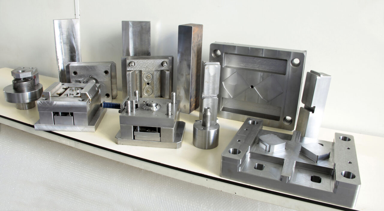
Tooling
Tooling risk incorporates Information from many other risk areas. Material selection, part design and labor all determine how the tooling is designed. The goal with this risk assessment is to make sure the tooling is going to work as expected and deliver the proper amount of parts for the expected life of the program. If we are going to run a million parts, we would never build tooling out of aluminum because it is soft and will wear out prematurely. PPT manufactures all of its tools to SPI specifications and since all tooling built and retained by PPT will be maintained at no cost to the customer, it is in our best interest to conduct a full risk analysis and mitigate any risks up front. This Risk category is deep and we look at all of the mechanical aspects of the tool design. For instance, tool steel, ejection, gating, sprue design, molding machine selection etc. We often utilize mold flow to mitigate tooling risk. PPT can take our tool design and run simulations with different processing parameters to give us a good idea on how the tooling will perform in real life. The image on the right is an example of a cooling analysis used to predict the performance of different core materials. Keep an eye out for more articles in the future on mold flow analysis.
Labor
We look at this section to mitigate risk associated with labor. Ideally when injection molding a part, we try to design the tooling so that the part will de-gate automatically which reduces the amount of labor required for the job and lowers cost. Sometimes, reducing the labor is not an option, for instance, when an operator has to hand load an insert for over molding. When it comes to labor risk, we have to look at the requirements of the job and ensure that we have the type of labor that is qualified to run the job. Does this job require skilled labor with specific technical expertise? Can the job be performed with unskilled labor? What happens when an operator fails to follow procedure? Take the hand-loaded insert example that I provided, what happens when the operator loads the insert wrong. Does it crash a multi-thousand dollar tool? If that is the case, we mitigate the risk by Pokeyoke’ing the tool to ensure the operator cannot fail.
Equipment
This section looks at all of the equipment required to produce the job, not just the molding machine but all equipment associated with the job. chillers, oil heaters, Hot Runner controllers, robots, driers and inspection equipment. We need to be able to prove that we have the required equipment to complete the job. If we don’t have the required equipment, would we be willing to purchase a piece of equipment? Probably, but it is important that we know what will be required of the job. It is obviously a good idea to review the tool design and insure that the size of the mold will fit into the machine that it will be quoted on right? What if the tool will physically fit in the machine, but the machine does not have enough capacity to fill the cavity with plastic? We have to look at all aspects when it comes to how the job will run in our factory.
Packaging
As you are probably well aware, PPT is a full service injection molder. We not only produce plastic parts, but we can produce finished goods. This means we can assemble, pouch, package, seal, label and ship finished products to the end user. When evaluating packaging we need to make sure that our methods can keep up with the cycle of the machine. We look at sourcing for pouches, any special labeling requirements and how to protect the assemblies during shipment. We don’t want the parts to be damaged during transit. Packaging requirements are different for every customer. Some customers specify a particular box size or weight, so we have to ensure that gets incorporated into the final product.
Application
In many cases we don’t know the end use of the product, but this is information that we always try to gather. We need to know if this is a critical safety item. PPT will try to look at how the part is going to function in the environment it is to be used in. Our customers know their products far better than we do but we will look for any red flags or risks that we can find. For instance, if we know this is an outdoor application but the customer has chosen a material that does not have any UV protection. PPT would identify that as a material risk and notify the customer.
Regulatory Concerns
Sometimes parts have a specific set of requirements that we have to plan for. Some medical parts may have more stringent FDA requirements than others and PPT will need to plan accordingly to ensure that we can meet the customers and the regulating body’s expectations. This category can encompass, regulatory or statutory concerns.
Special Quality Requirements
This is a very important section. We need to know the critical dimensions on the part and ensure that we have the capability to effectively measure the parts. What frequency will the parts need to be measured. Does the part have any special PPAP requirements, if so what level? Does it require OQ, PQ, IQ Validations. The goal is to identify the requirements before hand. This type of work can be bandwidth heavy and we need to plan accordingly. PPT will generally request a conversation with the customers Supplier Quality Engineer in order to get a better understanding on specific quality requirements related to the part. At the very least, we will review the customers Supplier quality manual, which generally provides incite into the customers quality requirements.
Closing Statement
Every project is different. We have large projects and small projects but the most important thing to remember is that they all begin with a thorough risk analysis aimed at ensuring the overall success of the program.
Thermoplastics are used in the vast majority of products manufactured today. Many of these products utilize screws, pins, and threaded inserts for fastening and joining; while these methods might be the best choice for assemblies requiring serviceability, there may be more cost-effective methods of assembly for those that don’t. In some cases, we can replace or eliminate fasteners by welding components together leading to reduced cost and less complexity. One common process that Plastics Plus Technology, Inc. can utilize to weld plastic components is called Ultrasonic Welding.
Ultrasonic welding is a process that utilizes high-frequency mechanical vibrations to generate frictional heat between two components. The heat generated causes the thermoplastic to melt at the mating surfaces and once cooled, creates a strong mechanical bond.
This process works well for many different types of thermoplastic polymers but all plastics are not good candidates for ultrasonic welding. The broad softening temperature of Amorphous thermoplastics makes them good candidates for welding. These materials include PC or ABS. Semi-crystalline materials like nylon can be welded but they are much less forgiving since they don’t have a broad softening point. It takes a lot more energy to make these materials melt since they have natural properties that will absorb the vibrations produced by the ultrasonic welding equipment. Material choice is very important when considering the option of ultrasonic welding.
On occasion, different types of materials may need to be welded together. In this case, an analysis of their mechanical properties, melt temperatures, and chemical compatibility should be completed to evaluate the effectiveness of the weld. Many materials will not weld together properly. PPT can offer guidance on what materials will work best.
How Does an Ultrasonic Welder Work?
Ultrasonic welders consist of several components: a piezoelectric transducer, a booster, and a sonotrode (horn). These parts are tuned to resonate at a specific ultrasonic frequency. The piezoelectric transducer (also known as a converter) changes electrical energy into mechanical vibrations. These vibrations are transmitted through a booster which modifies the amplitude of the vibration and transmits it into the sonotrode. The sonitrode is a tuned metal rod that focuses the ultrasonic vibrations into the parts. These vibrations cause friction that melts the parts together.
In this example, we will weld a lid onto a small box-like component. The operator places the component into the nesting fixture and places the lid on top. When the machine is cycled a ram moves the ultrasonically vibrating sonotrode or horn up against the parts. The nest securely holds the part in place while the lid is vibrated with the horn. After a short period of time, the weld is completed and the ram retracts moving the horn up where the cycle can be started again.
How to Know if Ultrasonic Welding is Right for You
Whether ultrasonic welding is right for you depends on a few factors:
If your product does not contain serviceable parts
Consists of two or more mating components
Needs to encase or house non-accessible electronics
Meets the material requirements (refer to material datasheet)
Features fasteners like screws, threads, pins, and more
Contact us and fill us in on our current assembly operation. Then we can determine a plan that might save you money in the long run.
Overmolding is the process of injection molding a component using two different materials. Typically a rigid material is overmolded with a soft thermoplastic elastomer(TPE). There are many different reasons why you may choose to overmold, these reasons include: styling, weatherproofing or ergonomics. There is no doubt that you have seen parts that have been produced in this manner. Your toothbrush is a perfect example as most tooth brushes are manufactured from a rigid polypropylene material and have softer TPE grips that are overmolded. TPE overmolds can be essential for critical applications where you need a non-slip grip or better control and tactile feel.
Other types of overmolding include insert molding. A screwdriver is a great example of an insert mold. The steel screwdriver is inserted into the mold and plastic is overmolded onto the steel creating a handle. In some cases the handles can be molded with several different materials to create a different look or feel.
Product Design Considerations
As with any injection molded product, Good product design is essential to reduce cost and improve the quality of the end product.
Wall thickness is important, a thick wall increases the cycle time and a thin wall can make your part feel flimsy.
Gradually transition from thick to thin sections to improve flow.
a wall thickness of .060″ to .120″ is typical for an overmolded TPE and will help to ensure that the overmold bonds to the substrate
Keep the wall thickness of the substrate and the overmold uniform, Core thick sections to reduce the chance of sinks or voids
Add a radius to Sharp corners to reduce stress in the molded part.
The TPE overmold should be less than or equal to the thickness of the substrate to prevent warp
Consider texturing the soft TPE, this reduces tendency to stick in the mold and can improve feel
Consider material selection, Some materials will bond together when overmolded. Other materials will require feature to mechanically fix the overmolded TPE to the substrate. These features can include undercuts or mechanical interlocks.
Material Considerations
You can overmold TPE over a variety of different materials. TPEs can be formulated to bond to different materials so it is important to work with the material supplier to select the most appropriate material for your application. Here is a short list of some of the materials commonly used as the base substrate in overmolded components:
Polycarbonate (PC)
ABS
PC/ABS
Nylons
Polystyrene
High impact Polystyrened
Acetal
PPO
Polypropylene
Tooling Design Considerations
The tooling design will be heavily dependent on your estimated annual volumes and target pricing. For very high volume parts with a low target cost, we would select tooling capable of running fully automatic. This would require specialized molding machines with multiple barrels capable of shooting more than one material at a time. The tooling is specialized and designed to fit a particular machine. These types of molds can be very expensive.
For lower volume parts, an operator or robot can manually place the substrate into the tooling and overmold the soft material. This process will require two tools, one to produce the substrate and another to produce the overmold. This can be done in a typical molding machine using a single barrel but would require multiple setups and a full time operator. The cost is higher but this is a better option for lower volume parts.
Plastics Plus Technology Inc, has worked closely with one of our partners to develop 3d printed mold cavities for evaluating new injection molded part designs. With the help of our tool room PPT was able to configure a retired mud mold to accept 3d printed cores and cavities for use in prototype development.
The 3d printed cavities have been very helpful in market testing and bringing products to market quickly without the expense of a full blown injection mold tool. Currently we are producing small prototype parts from TPE materials but there is potential to create parts from ABS or other materials in future products. There are limitations on what types of materials we can ruwith the 3d printed cavities. For instance, high temperature engineering grade materials are not good candidates for cavities produced from this particular material. Generally materials with lower melt temps work best for use in 3d printed molds utilizing this technology. The cavities have poor cooling characteristics and the cycle times can be very long.
The 3D printed cores and cavities were produced with Vero white material on a Stratasys Polyjet 3D printer. This printer uses a process called photopolymerization to print objects. The photosensitive Verowhite resin material is applied layer by layer and cured with a UV light to create a very detailed and high resolution object. Parts and cavities produced with this kind of technology can have very good surface finish when compared to other 3d printed technology.
There are some design considerations to consider when developing parts that will use 3d printed mold cavities:
The cycle time is very long. 3d printed cavities do not have the same cooling characteristics as typical mold tooling.
Not all materials are good candidates for 3d printed cavities. High temperature materials do not work well
Make sure the parts have adequate draft, at least 5 degrees draft is recommended
Make sure any engraving or embossing is large enough to fill properly
Cavities may require polish to eliminate layer lines
Mold release may be required to prevent sticking of parts
Ejection should be thought of in advance, how do you plan on removing the part. TPEs can be pulled from cavity easily while ABS or rigid materials may require pin ejection
Plastics Plus Technology is a woman-owned, USA contract manufacturer based in sunny Southern California. Our custom injection molding and value-added services can provide you with a one-stop job shop for all your plastic manufacturing needs.
ISO 9001:2015, ISO 13485:2016 QMS certified and compliant. FDA compliant. Good Manufacturing Practices (GMPs). WBENC.